Picture 1
Interesting results from practical cam lobe calculations
www.gaenssle.de
The results shown here clearly show the huge potential
an optimum cam lobe calculation has. As a side effect, we will see that one cannot determin how "hot" a cam is, or how the valve lift diagram is by just looking at the cam lobe. As we all know, the valve lift diagram describes the valve lift over the crankshaft angle.
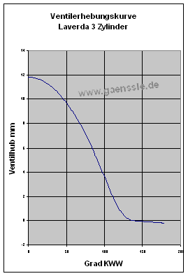
Using our unique cam profile calculating software KnockSoft, we calculated the ideal valve lift diagram for a Laverda triple bored out to 1200 cc. The customer wanted a wide power range whith good bottom end power. Here the result as a half curve, picture 1:

Picture 1
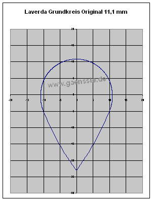
Now that we had the ideal valve lift curve, the next step was to calculate the cam lobe. After entering the geometrical data of the engine, like distance between the bottom of the bucket tappets and cam axis etc., our cam calculating software KnockSoft provides the corresponding cam lobe form. The result shown in picture 2 is sobering, though:

Picture 2
The calculated cam lobe looks very unusual, yet generates the desired valve lift curve as shown in picture 1. It is obvious that at the top of the cam lobe (there is no radius to speak of) the pressure per contact area would be much too high. The engine would run at full power, but the durability of the cam would be very low.
Now we are facing a serious problem. The valve lift of astonishing 11.8 mm could only be achieved along with unacceptable durability. For comparison, the hottest Laverda performance cam has a valve lift of just 9 mm.
It is impossible to realize the ideal valve lift curve because of the geometric environment of that engine!
What are the options?
The only logical conclusion is to alter the geometric properties of the engine. In that case, using camshaft carriers with an offset camshaft axis might help. Here we clearly see the advantages of nowadays technology: We can cost effectively explore possible solutions on the computer instead of having to manufacture test cams just to see they do not work.
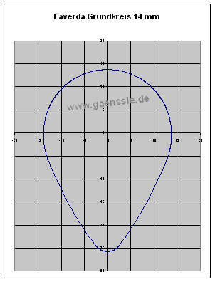
In the next run KnockSoft calculated such a possible solution: The cam's center axis is offset 3 mm away from the valve in direction of the valve axis. This results in wider radii and lower pressure per contact area.
Calculating the cam lobe with KnockSoft solves the problem. The result, as shown in picture 3, is much more
appaling:

Picture 3
Remarkably, the cam lobe shown in picture 3 generates the same valve lift curve as the extremely pointed cam lobe in picture 2.
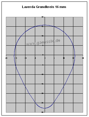
In a third run, the camshaft axis was offset for additional 2 mm. Picture 4:

Picture 4
Now we have an ideal cam lobe design, based on which we could actually machine the cam. On the engine, it was necessary to offset the camshaft axis.
Below the three cam lobes are shown for comparison.
All three cam lobes produce the same valve lift curve!


A word of caution! Please du not take this as a general performance hint for Laverda and simply install a cam with a base circle of 16 mm and 12 mm lift. The exact lobe form must be correct within hundreds of millimeters, otherwise the risk is heavy damage! This will not work without precise calculation.